Locomotive Shop
GP9, GP20 And The RSC
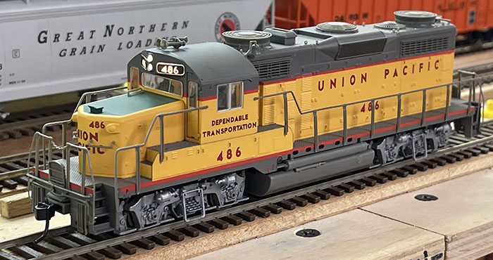 Proto 2000 early GP20 and GP9 were much the same under the hood.
 Here is the inside of the Proto 2000, not much room for a DCC Decoder.
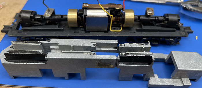 I I removed the weight which is held on each end and with 2 bolts up thru the fuel tank. The Fuel tank bolts mostly had a pink shake proofing which needed a little work to remove.
With the weight removed A location was found to mill space for a nice little NCE decoder. So this weight went on to the vertical milling machine and the result looked like this:
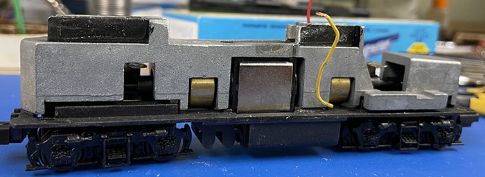 An additional hole had to be drilled and threaded into the weight which was needed to supply a connection point for the frame power off the Engineer's rail side. The tabs on the trucks provided the Fireman's side.
 The wiring spaces for power and lighting of the Proto 2000 allowed paths of new wires to be installed. The NCE decoder was placed on a 2-sided tape and used the 9-pin socket supplied with the decoder. The wires from the socket are long enough to use to connect the power (Red Engineer's side Black to the Fireman's side Orange to the + on the motor and Gray to the insolated motor wire of the 2000 frame.) I use a 12-volt LEDs from Litchfield Station and the 9 pin plug wires (white to the headlight and Yellow to the rear light, with a blue + common wire) to connect to the LED wires that were cut short. All wire connections were covered with 1 mm shrink tube and then both LED wires were covered by 3 mm black shrink tube all the way up to the end of the LED. The LEDs were placed into the locations supplied by the Proto 2000 design.
 With a little adjustment of the wires, like slipping the motor wire to take its place in the slot provided, you can put the body back on the frame.
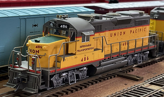 Here is the GP20 with all the new details in place.
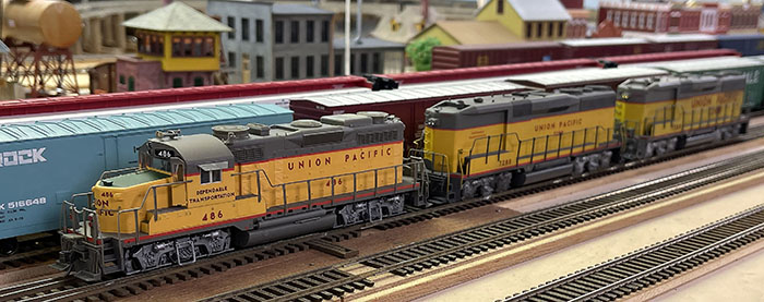 This GP20 with 2 GP30B units are painted in different era's paint designs.
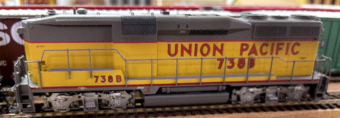
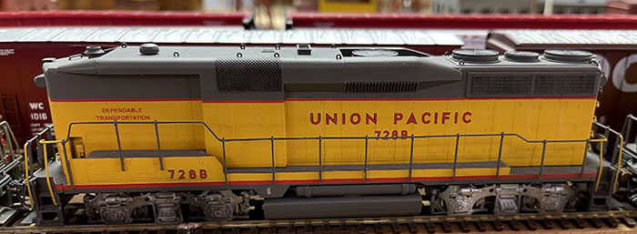
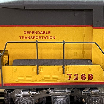
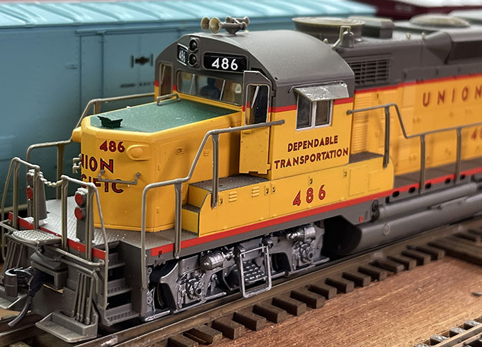 Here is a close up of additional details.
Return to the Locomotive Workshop (Click Here)
Work Shop Home (Click Here)
Join us in the “Greatest Hobby” as a member of the TLMRC.
Site home (Click Here)

